
I was fidding with the steering to get my heater core out and i accidently popped out the bushing that the steering colum goes through thats at the firewall, how should i apprach getting it back in or is this a job for an actual mechanic
Give it a try yourself. And you are still left with the option to take it to a mechanic.
Steering Column Installation Video

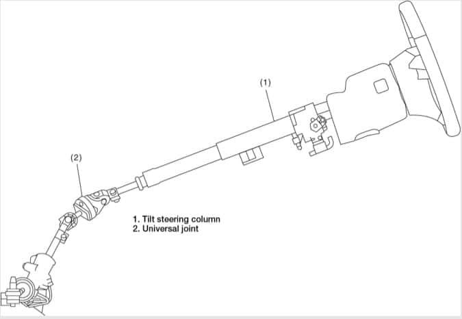
Tilt Steering Column Removal
- Remove the steering wheel as follows:
- Disconnect the ground cable from battery.
- Set the tire to the straight-ahead position.
- Remove the airbag module as outlined in the Chassis Electrical Section.
WARNING Always refer to “Airbag System” before performingservice on the airbag modules as outlined in the Chassis Electrical Section.
- Place alignment marks on the steering wheeland steering shaft.
- Remove the steering wheel nut, and then drawout the steering wheel from shaft using steeringpuller.
- Remove the universal joint as follows:
- Remove the steering wheel as outlined above.
- Place alignment marks on universal joint.
- Remove the universal joint bolt and remove theuniversal joint.
- Remove the instrument panel lower cover under.
- Remove the instrument panel lower cover upper.
- Remove all connectors from the steering column.
- Remove the two bolts under instrument panelsecuring the steering column.
- Pull out the steering shaft assembly from thehole on toe board.
CAUTION - Be sure to remove the universal joint beforeremoving steering shaft assembly installingbolts when removing steering shaft assemblyor when lowering it for servicing other parts.
- Do not loosen the tilt lever when the steeringcolumn is not secured to the vehicle.

To install:
- Install the grommet to the toe board.
- Insert the end of the steering shaft into the toeboard grommet.
- With the tilt lever secured, tighten the steeringshaft mounting bolts under instrument panel. Tighten bolts to 18 ft. lbs. (25 Nm)
- Connect all the connectors under the instrumentpanel.
- Connect the airbag system connector at the harnessspool.
NOTE Make sure to apply double lock.
- Install the instrument panel lower cover with tiltlever held in the lowered position.
- Install the universal joint as follows:
- Align the cutout portion at serrated section of thecolumn shaft and yoke, then install the universaljoint into column shaft.
- Install the universal joint to the serrations ofgearbox assembly by matching alignment marks.
- Tighten the bolts to 18 ft. lbs. (24 Nm)
CAUTION Excessively large tightening torque of universaljoint bolts may lead to heavy steering wheeloperation. Clearance between coupling of universal jointand turbo cover: 0.59 inch (15 mm) or more.
- Align the center position of the roll connector as follows:
- Check that front wheels are positioned in straightahead direction.
- Turn the roll connector pin clockwise until itstops.
- Turn the roll connector pins approx. 3.25turns in the counterclockwise direction until “ ”marks are aligned.
- Install the steering wheel as outlined below.
- Install the steering wheel as follows:
WARNING Always refer to “Airbag System” before performingservice on the airbag modules as outlined in the Chassis Electrical Section.
- Align the center position of the roll connector as outlined above.
- Install the airbag module as outlined in the Chassis Electrical Section.
- Set the tire to the straight-ahead position.
- Connect the ground cable from battery.
WARNING Always refer to “Airbag System” before performingservice on the airbag modules as outlined in the Chassis Electrical Section.
- Align marks placed on the steering wheeland steering shaft before removal.
- Install the steering wheel to the shaft using steering puller, and then install the nut.
NOTE Align the alignment marks on the steering wheeland steering shaft.
- Tighten bolts to 29 ft. lbs. (39 Nm). Column cover-to-steering wheel clearance:0.08–0.16 in (2–4 mm)
CAUTION Insert the roll connector guide pin into theguide hole on the lower end of the steeringwheel surface. Avoid damaging the pin.