Instructions on removal of Instrument Panel to access HVAC Blend Door Actuator
INSTRUMENT PANEL REMOVAL
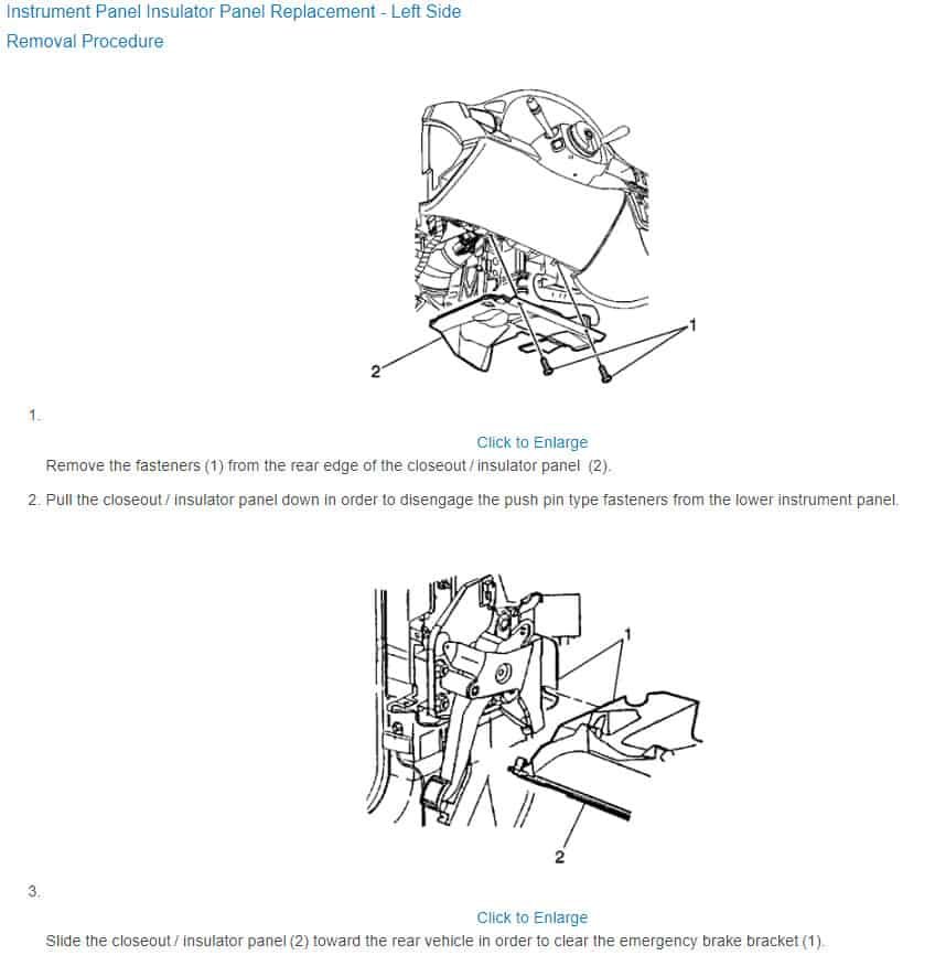
- Remove left and right closeout insulator panel mounting screws.
- Remove left and right closeout insulator panels by pulling panel downward to disconnect push pin fasteners, then slide panels rearward.

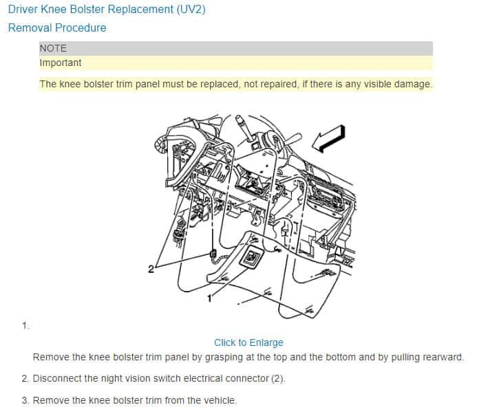
- Remove lefthand knee bolster mounting screws.

- Grasp top and bottom of lefthand knee bolster trim panel, then pull rearward to remove from instrument panel.
- Grasp top and bottom of righthand knee bolster trim panel, then pull rearward to remove from instrument panel.
- On models except DTS, remove center storage compartment mounting screws, then storage compartment. Disconnect electrical connector.
- On DTS models, proceed as follows:
a. Remove two mounting screws at bottom of center storage compartment.
b. Open compartment door, then pull inside of compartment rearward to release upper retainers.
c. Disconnect electrical connector and remove compartment. - On all models, remove console as outlined in Floor Console.
- Remove end caps from left and right sides of instrument panel with a suitable flat bladed tool.
- Pry rear edge of defroster grille upward with a suitable flat bladed tool.
- Disconnect sunload sensor electrical connector, then remove defroster grille by prying rear edge up.
- Remove windshield pillar garnish molding.
- Remove air outlet vents by releasing retainers at top and bottom of air outlet housing using a suitable flat bladed tool. Air outlet vents are not interchangeable, record vent location during removal.
- Remove four upper pad mounting screws located inside vent outlet openings, then three mounting bolts inside defroster grille openings.
- Lift upper pad upward from rear edge of instrument cluster and disengage cluster retainers.
- Disconnect cluster electrical connectors.
- Lift upper trim pad on an angle, then slide pad rearward to disengage front retainers.
- Disconnect body to instrument panel electrical connectors.
- Disconnect steering column electrical connectors, then remove steering column to body mounting bolts.
- Remove transaxle park/neutral position switch lever cable end cap.
- Pry cable lock button to unlocked position, then remove cable from bracket.
- Remove shift control cable from floor shift, then disconnect from steering column.
- Remove instrument panel center support bracket to floor bracket mounting bolts.
- Remove instrument panel to cowl mounting nuts.
- Remove instrument panel to hinge pillar mounting bolts and nuts.
- Remove instrument panel.
- Reverse procedure to install, noting following:
a. Torque accelerator pedal to 84 inch lbs.
b. Torque air outlet deflector to 18 inch lbs.
c. Torque armrest switch plate to 13 inch lbs.
d. Torque defroster grille to 18 inch lbs.
e. Torque driver’s side air bag inflatable module to 27 inch lbs.
f. Torque end brace to 84 inch lbs.
g. Torque foot rest base to 18 inch lbs.
h. Torque glove compartment to 18 inch lbs.
i. Torque heater & A/C control to 18 inch lbs.
j. Torque hood release latch to 53 inch lbs.
k. Torque insulator panel to 18 inch lbs.
l. Torque intermediate Steering Shaft to 35 ft. lbs.
m. Torque instrument cluster to 18 inch lbs.
n. Torque instrument panel to 18 inch lbs.
o. Torque instrument panel to bracket, lower to 97 inch lbs.
p. Torque instrument panel to dash panel to 80 inch lbs.
q. Torque instrument panel to tie bar to 18 inch lbs.
r. Torque intermediate shaft pinch bolt to 35 ft. lbs.
s. Torque knee bolster bracket to 80 inch lbs.
t. Torque park brake pedal to 18 ft. lbs.
u. Torque passenger’s side air bag inflatable module to 18 inch lbs.
v. Torque radio to 44 inch lbs.
w. Torque sound insulator to 18 inch lbs.
x. Torque steering column bracket to 12 ft. lbs.
y. Torque steering column opening filler bracket to 18 inch lbs.
z. Torque steering column support, lower to 84 inch lbs.
aa. Torque steering column support, upper to 20 ft. lbs.
ab. Torque steering wheel to 30 ft. lbs.
ac. Torque trim bezel to 4 inch lbs.
ad. Torque trim panel cover to 18 inch lbs.

Sounds good, very detailed.
I’d be happy to make a contribution via PayPal as suggested, but don’t I can really tackle this job without some kind of diagram to make the instructions useful.
I know what “knee bolsters” are and can probably figure out some of the other references once in there. But terms like “closeout insulator panel” and “windshield pillar garnish molding” are pretty obscure. There must be an illustration or diagram being referenced here that would make the instructions clearer.
Updated the information with what i could come up with in the Free Resources.
These diagrams are kind of basic in appearance. The Premium diagrams are much better. Well worth the $20 in my opinion.
FOLLOW THIS LINK TO> Purchase the PREMIUM ONLINE Auto Repair Manual for only $19.95
You won't be disappointed and the cars wiring diagrams are included with the manual.
Your FreeAutoMechanic,
Jaxer
Comments are closed.