
White smoke out of exhaust at startup, then no smoke until it has been setting for a while after driving
Short Answer: Blown Head Gasket or intake leak.
White smoke is an indication of coolant passing through the engine and being burned. The description you gave indicates it is at the beginning stage and will only get worse if left alone. You are able to check your coolant level to see just how much coolant you are going through now. One quick fix you can try is Bar’s Stop Leak. Just add it to the radiator and drive. I have had great success with this product on many occasions for sealing up intake and water pump leaks. I would try this product first and see if it saves you from having to replace the head gasket/s.
Should you need to replace the head gasket I have provided the procedure below for both the 2.5L engine and the 3.5L engine. Hopefully you won’t have to go that route. It could get expensive. Here is a video I made using the product and the leak has not returned. Worth trying for the money and time you could save in my opinion.
Head Gasket Replacement Labor Time
- 2.5L engine head gasket labor = 13.8
- 3.5L engine head gasket labor = 15.7

2.5L ENGINE CYLINDER HEAD GASKET R&R
REMOVAL
Refer to Fig. 1 for exploded view of cylinder head gasket components replacement.
- Remove timing chain.
- Remove camshafts.
- Next Remove spark plugs.
- Remove intake manifold.
- Remove exhaust manifold and three way catalyst.
- Loosen cylinder head bolts in reverse order as illustrated, using power tool, Fig. 2.
- Remove cylinder head.
- Remove cylinder head gasket.
- Replace cylinder head bolts with new ones if size difference between d1 and d2 exceeds limit, Limit (d1-d2) is 0.23 mm (0.0091 inch) or more, Fig. 3.
- If reduction of outer diameter appears in a position other than d2, use it as d2 point, Fig. 3.
INSTALLATION
Reverse procedure to install. Note following: - Clean surfaces of cylinder head and cylinder block.
- Install a new cylinder head gasket. Caution: Do not reuse cylinder head gasket.
- Install cylinder head.
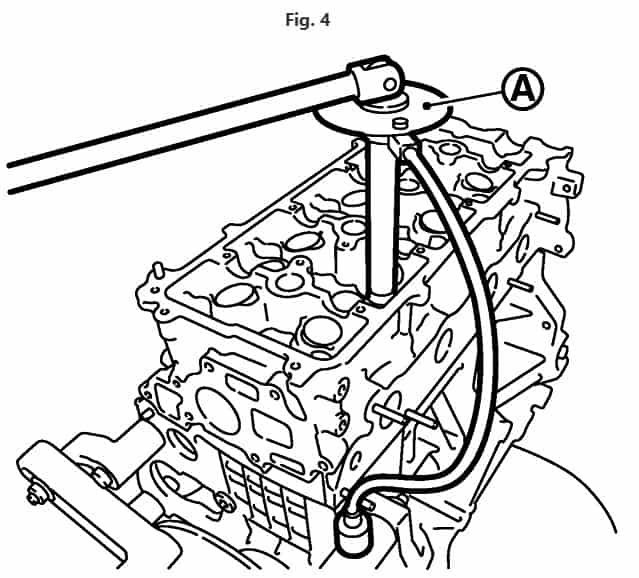
- Follow steps below to tighten cylinder head bolts in numerical order as illustrated, Fig. 4.
- Clean threads and seating surfaces of bolts.
- Apply new engine oil to threads and seating surfaces of bolts. Caution: If cylinder head bolts are re-used, inspect their outer diameters before installation. Follow outer diameter of cylinder head bolts measurement procedure. Check and confirm tightening angle by using angle wrench or protractor. Do not judge angle by visual inspection.
- Torque cylinder head bolts to 50 Nm. (5.1 kg-m., 37 ft. lbs.), plus an additional 60 degrees clockwise, Fig. 2.
- Loosen all cylinder head bolts to 0 Nm., in reverse order of tightening.
- Torque cylinder head bolts to 39.2 Nm. (4 kg-m., 29 ft. lbs.), plus an additional 75 degrees turn, and an additional 75 degrees turn, Fig. 2.


3.5L ENGINE CYLINDER HEAD GASKET R&R
REMOVAL
Refer to Fig. 1 for exploded view of cylinder head gasket components replacement.
- Remove rear timing chain case.
- And Remove intake manifold.
- Next Remove intake and exhaust camshafts.
- Remove exhaust manifold and three way catalyst (bank 1 / bank 2).
- Then Remove coolant outlet housing.
- Remove righthand and lefthand cylinder head bolts, with power tool.
- Bolts should be loosened gradually in three stages.
- Loosen bolts in numerical order.
- Remove cylinder heads and gaskets.
- Discard cylinder head gaskets and use new gaskets for installation.
INSTALLATION
Reverse procedure to install. Note following: - Turn crankshaft until No. 1 piston is set at Top Dead Center (TDC) on compression stroke.
- Crankshaft key should line up with righthand bank cylinder center line as illustrated.
- Install new gaskets on cylinder heads.
- Inspect cylinder head bolts before installing cylinder heads.Caution: Cylinder head bolts are tightened by degree rotation tightening method. Whenever size difference between d1 and d2 exceeds limit, replace bolts with new ones. Lubricate threads and seat surfaces of bolts with new engine oil, Fig. 6. Limit (“d1” – “d2” is 0.11 mm (0.0043 inch).
- Install cylinder heads on cylinder block. Tighten cylinder head bolts in five steps in numerical order as illustrated using tool no. KV10112100 (BT-8653-A), or equivalent.
- Torque cylinder head bolts to 98.1 Nm. (10 kg-m., 72 ft. lbs.).
- Now, loosen all bolts in reverse order of tightening.
- Torque cylinder head bolts to 39.2 Nm. (4 kg-m., 29 ft. lbs.), plus an additional 103 degrees turn clockwise, and an additional 103 degrees turn clockwise.
