
Electrical Testing with a Multi meter


Troubleshooting and Testing Electrical Systems with a Multi meter
When diagnosing a specific problem, organized troubleshooting is a must. The complexity of a modern automotive vehicle demands that you approach any problem in a logical, organized manner. There are certain troubleshooting techniques, however, which are standard:
- Establish when the problem occurs. Does the problem appear only under certain conditions? Were there any noises, odors or other unusual symptoms? Isolate the problem area. To do this, make some simple tests and observations, then eliminate the systems that are working properly. Check for obvious problems, such as broken wires and loose or dirty connections. Always check the obvious before assuming something complicated is the cause.
- Test for problems systematically to determine the cause once the problem area is isolated. Are all the components functioning properly? Is there power going to electrical switches and motors. Performing careful, systematic checks will often turn up most causes on the first inspection, without wasting time checking components that have little or no relationship to the problem.
- Test all repairs after the work is done to make sure that the problem is fixed. Some causes can be traced to more than one component, so a careful verification of repair work is important in order to pick up additional malfunctions that may cause a problem to reappear or a different problem to arise. A blown fuse, for example, is a simple problem that may require more than another fuse to repair. If you don't look for a problem that caused a fuse to blow, a shorted wire (for example) may go undetected.
Experience has shown that most problems tend to be the result of a fairly simple and obvious cause, such as loose or corroded connectors, bad grounds or damaged wire insulation which causes a short. This makes careful visual inspection of components during testing essential to quick and accurate troubleshooting.
TESTING OPEN CIRCUITS
Fig. 1: The infinite reading on this multi meter indicates that the circuit is open
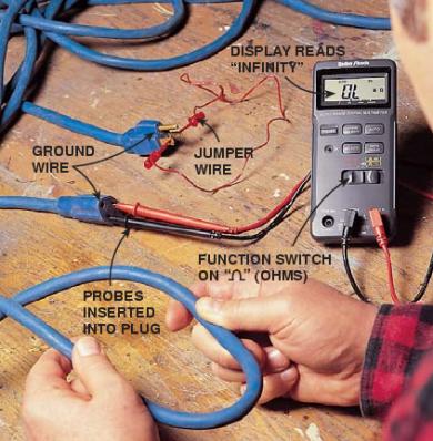
This test already assumes the existence of an open in the circuit and it is used to help locate the open portion.
- Isolate the circuit from power and ground.
- Connect the self-powered test light or ohmmeter ground clip to the ground side of the circuit and probe sections of the circuit sequentially.
- If the light is out or there is infinite resistance, the open is between the probe and the circuit ground.
- If the light is on or the meter shows continuity, the open is between the probe and the end of the circuit toward the power source.
SHORT CIRCUITS
NOTE: Never use a self-powered test light to perform checks for opens or shorts when power is applied to the circuit under test. The test light can be damaged by outside power.
- Isolate the circuit from power and ground.
- Connect the self-powered test light or ohmmeter ground clip to a good ground and probe any easy-to-reach point in the circuit.
- If the light comes on or there is continuity, there is a short somewhere in the circuit.
- To isolate the short, probe a test point at either end of the isolated circuit (the light should be on or the meter should indicate continuity).
- Leave the test light probe engaged and sequentially open connectors or switches, remove parts, etc. until the light goes out or continuity is broken.
- When the light goes out, the short is between the last two circuit components which were opened.
VOLTAGE
This test determines voltage available from the battery and should be the first step in any electrical troubleshooting procedure after visual inspection. Many electrical problems, especially on computer controlled systems, can be caused by a low state of charge in the battery. Excessive corrosion at the battery cable terminals can cause poor contact that will prevent proper charging and full battery current flow.
- Set the voltmeter selector switch to the 20V position.
- Connect the multi meter negative lead to the battery's negative (-) post or terminal and the positive lead to the battery's positive (+) post or terminal.
- Turn the ignition switch ON to provide a load.
- A well charged battery should register over 12 volts. If the meter reads below 11.5 volts, the battery power may be insufficient to operate the electrical system properly.
VOLTAGE DROP
When current flows through a load, the voltage beyond the load drops. This voltage drop is due to the resistance created by the load and also by small resistance's created by corrosion at the connectors and damaged insulation on the wires. The maximum allowable voltage drop under load is critical, especially if there is more than one load in the circuit, since all voltage drops are cumulative.
- Set the voltmeter selector switch to the 20 volt position.
- Connect the multi meter negative lead to a good ground.
- Operate the circuit and check the voltage prior to the first component (load).
- There should be little or no voltage drop in the circuit prior to the first component. If a voltage drop exists, the wire or connectors in the circuit are suspect.
- While operating the first component in the circuit, probe the ground side of the component with the positive meter lead and observe the voltage readings. A small voltage drop should be noticed. This voltage drop is caused by the resistance of the component.
- Repeat the test for each component (load) down the circuit.
- If a large voltage drop is noticed, the preceding component, wire or connector is suspect.
Testing if a diode is OK
A diode is like a one-way valve. It should allow the current to only flow in one direction and prevent the
current from flowing in the other direction. A good
diode should show continuity in one direction and no
continuity (or over range) in the other.
Do not test the diode whilst there is an external voltage
(eg solar panel) connected as this will effect the
outcome and possibly damage the meter.
Connect the probes to the device you want to check and
note the meter reading. Reverse the probes and note the
second reading. If the one reading shows some value
and the other is over range, the device is good. If both
readings are over range, the device is faulty (open
circuit). If both readings are very small or zero, the
device is also faulty (short circuit).
Testing for Continuity
In order to measure continuity you need to have a
voltage source.
If there is a poor connection or a break in the house
wiring it can often be located by tracing the wires from
the battery bank outwards and using the battery bank as
your voltage source.
With the meter on the appropriate voltage scale start by
measuring the voltage at the battery. Now move to the
next location where you can connect your probes as you
head towards the possible location of the fault.
If at any point you measure no voltage then there is a
break in the wiring between the previous test point and
this one.
If you measure a drastic voltage drop (particularly with
a small load turned on) this may indicate a poor
connection such as a wire that is almost broken,
corrosion in a connector or a wire, or it may be due to
undersized wiring.