
Automotive Wiring Test Equipment


Test Equipment
Pinpointing the exact cause of trouble in an electrical circuit is most times accomplished by the use of special test equipment. The following describes different types of commonly used test equipment and briefly explains how to use them in diagnosis. In addition to the information covered below, the tool manufacturer's instructions booklet (provided with the tester) should be read and clearly understood before attempting any test procedures.
JUMPER WIRES
CAUTION
Never use jumper wires made from a thinner gauge wire than the circuit being tested. If the jumper wire is of too small a gauge, it may overheat and possibly melt. Never use jumpers to bypass high resistance loads in a circuit. Bypassing resistances, in effect, creates a short circuit. This may, in turn, cause damage and fire. Jumper wires should only be used to bypass lengths of wire or to simulate switches.
Jumper wires are simple, yet extremely valuable, pieces of test equipment. They are basically test wires which are used to bypass sections of a circuit. Although jumper wires can be purchased, they are usually fabricated from lengths of standard automotive wire and whatever type of connector (alligator clip, spade connector or pin connector) that is required for the particular application being tested. In cramped, hard-to-reach areas, it is advisable to have insulated boots over the jumper wire terminals in order to prevent accidental grounding. It is also advisable to include a standard automotive fuse in any jumper wire. This is commonly referred to as a "fused jumper". By inserting an in-line fuse holder between a set of test leads, a fused jumper wire can be used for bypassing open circuits. Use a 5 amp fuse to provide protection against voltage spikes.
Jumper wires are used primarily to locate open electrical circuits, on either the ground (-) side of the circuit or on the power (+) side. If an electrical component fails to operate, connect the jumper wire between the component and a good ground. If the component operates only with the jumper installed, the ground circuit is open. If the ground circuit is good, but the component does not operate, the circuit between the power feed and component may be open. By moving the jumper wire successively back from the component toward the power source, you can isolate the area of the circuit where the open is located. When the component stops functioning, or the power is cut off, the open is in the segment of wire between the jumper and the point previously tested.
You can sometimes connect the jumper wire directly from the battery to the "hot" terminal of the component, but first make sure the component uses 12 volts in operation. Some electrical components, such as fuel injectors or sensors, are designed to operate on about 4 to 5 volts, and running 12 volts directly to these components will cause damage.
TEST LIGHTS
Fig. 1: A 12 volt test light is used to detect the presence of voltage in a circuit
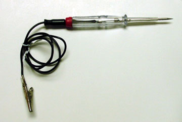
The test light is used to check circuits and components while electrical current is flowing through them. It is used for voltage and ground tests. To use a 12 volt test light, connect the ground clip to a good ground and probe wherever necessary with the pick. The test light will illuminate when voltage is detected. This does not necessarily mean that 12 volts (or any particular amount of voltage) is present; it only means that some voltage is present. It is advisable before using the test light to touch its ground clip and probe across the battery posts or terminals to make sure the light is operating properly.
WARNING
Do not use a test light to probe electronic ignition, spark plug or coil wires. Never use a pick-type test light to probe wiring on computer controlled systems unless specifically instructed to do so. Any wire insulation that is pierced by the test light probe should be taped and sealed with silicone after testing.
Like the jumper wire, the 12 volt test light is used to isolate opens in circuits. But, whereas the jumper wire is used to bypass the open to operate the load, the 12 volt test light is used to locate the presence of voltage in a circuit. If the test light illuminates, there is power up to that point in the circuit; if the test light does not illuminate, there is an open circuit (no power). Move the test light in successive steps back toward the power source until the light in the handle illuminates. The open is between the probe and a point which was previously probed.
The self-powered test light is similar in design to the 12 volt test light, but contains a 1.5 volt penlight battery in the handle. It is most often used in place of a multimeter to check for open or short circuits when power is isolated from the circuit (continuity test).
The battery in a self-powered test light does not provide much current. A weak battery may not provide enough power to illuminate the test light even when a complete circuit is made (especially if there is high resistance in the circuit). Always make sure that the test battery is strong. To check the battery, briefly touch the ground clip to the probe; if the light glows brightly, the battery is strong enough for testing.
NOTE: A self-powered test light should not be used on any computer controlled system or component. The small amount of electricity transmitted by the test light is enough to damage many electronic automotive components.
MULTIMETERS
Multimeters are an extremely useful tool for troubleshooting electrical problems. They can be purchased in either analog or digital form and have a price range to suit any budget. A multimeter is a voltmeter, ammeter and ohmmeter (along with other features) combined into one instrument. It is often used when testing solid state circuits because of its high input impedance (usually 10 megaohms or more). A brief description of the multimeter main test functions follows:
- Voltmeter — the voltmeter is used to measure voltage at any point in a circuit, or to measure the voltage drop across any part of a circuit. Voltmeters usually have various scales and a selector switch to allow the reading of different voltage ranges. The voltmeter has a positive and a negative lead. To avoid damage to the meter, always connect the negative lead to the negative (-) side of the circuit (to ground or nearest the ground side of the circuit) and connect the positive lead to the positive (+) side of the circuit (to the power source or the nearest power source). Note that the negative voltmeter lead will always be black and that the positive voltmeter will always be some color other than black (usually red).
- Ohmmeter — the ohmmeter is designed to read resistance (measured in ohms) in a circuit or component. Most ohmmeters will have a selector switch which permits the measurement of different ranges of resistance (usually the selector switch allows the multiplication of the meter reading by 10, 100, 1,000 and 10,000). Some ohmmeters are "auto-ranging" which means the meter itself will determine which scale to use. Since the meters are powered by an internal battery, the ohmmeter can be used like a self-powered test light. When the ohmmeter is connected, current from the ohmmeter flows through the circuit or component being tested. Since the ohmmeter's internal resistance and voltage are known values, the amount of current flow through the meter depends on the resistance of the circuit or component being tested. The ohmmeter can also be used to perform a continuity test for suspected open circuits. In using the meter for making continuity checks, do not be concerned with the actual resistance readings. Zero resistance, or any ohm reading, indicates continuity in the circuit. Infinite resistance indicates an opening in the circuit. A high resistance reading where there should be none indicates a problem in the circuit. Checks for short circuits are made in the same manner as checks for open circuits, except that the circuit must be isolated from both power and normal ground. Infinite resistance indicates no continuity, while zero resistance indicates a dead short.
WARNING
Never use an ohmmeter to check the resistance of a component or wire while there is voltage applied to the circuit.
- Ammeter — an ammeter measures the amount of current flowing through a circuit in units called amperes or amps. At normal operating voltage, most circuits have a characteristic amount of amperes, called "current draw'' which can be measured using an ammeter. By referring to a specified current draw rating, then measuring the amperes and comparing the two values, one can determine what is happening within the circuit to aid in diagnosis. An open circuit, for example, will not allow any current to flow, so the ammeter reading will be zero. A damaged component or circuit will have an increased current draw, so the reading will be high. The ammeter is always connected in series with the circuit being tested. All of the current that normally flows through the circuit must also flow through the ammeter; if there is any other path for the current to follow, the ammeter reading will not be accurate. The ammeter itself has very little resistance to current flow and, therefore, will not affect the circuit, but it will measure current draw only when the circuit is closed and electricity is flowing. Excessive current draw can blow fuses and drain the battery, while a reduced current draw can cause motors to run slowly, lights to dim and other components to not operate properly.
Fig 2. Basic Multi-meter