
(O2) Oxygen Sensor
Oxygen Sensor (O2)
OPERATIONThe oxygen sensor has the ability to produce a low voltage signal that feeds information on engine exhaust oxygen content to the control module.
The sensor is constructed from a zirconia/platinum electrolytic element. Zirconia is an electrolyte that conducts electricity under certain chemical conditions. The element is made up of a ceramic material which acts as an insulator when cold. At operating temperatures of approximately 600°F (315°C), the element becomes a semiconductor. A platinum coating on the outer surface of the element stimulates further combustion of the exhaust gases right at the surface and this helps to keep the element up to the desired temperature.
The oxygen sensor has an inner cavity which is filled with reference (atmospheric) air. The atmosphere has approximately 21 percent oxygen in it. In the circuit, this inner cavity is the positive terminal, while the outer surface (exposed to the exhaust stream) is the negative or ground terminal.
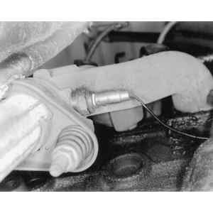
Fig. 1: The oxygen (O2) sensor is threaded into the exhaust manifold
Due to the element's electrolytic properties, oxygen concentration differences between the reference air and exhaust gases produce small voltages. A rich exhaust (excess fuel) has almost no oxygen. So when there is a large difference in the amount of oxygen touching the inside and outside surfaces, more conduction occurs and the sensor puts out a voltage signal above 0.6 V (600 mV). The signal may vary as high as 0.9 V (999 mV).
With a lean exhaust (excessive oxygen), there is about 2 percent oxygen in the gases. The smaller difference in oxygen content causes less conduction and the sensor produces a smaller voltage somewhere below 0.3 V (300 mV). The signal could drop as low as 0.1 V (100 mV). Commonly, values outside this range will cause a trouble code to set for most control systems. When handling the oxygen sensor, follow these precautions:
•Careful handling of the oxygen sensor is essential.
•The electrical pigtail and connector are permanently attached and should not be removed from the oxygen sensor.
•The in-line electrical connector and louvered end of the oxygen sensor must be kept free of grease, dirt and other contaminants.
•Avoid using cleaning solvents of any type on the oxygen sensor.
•Do not drop or roughly handle the oxygen sensor.
•The oxygen sensor may be difficult to remove if the engine temperature is below 120°F (48°C). Excessive force may damage the threads in the exhaust manifold or exhaust pipe.
Oxygen Sensor Related Symptoms
- Surging at idle
- Unstable idle
- Running rough off idle
- Hesitation
- Stumble
- Chuggle
- Poor fuel economy
- Spark knock
- Stalling on acceleration
Oxygen Sensor Testing
Single Wire Sensor
- Start the engine and bring it to normal operating temperature, then run the engine above 1200 rpm for two minutes.
- Backprobe with a high impedance averaging voltmeter (set to the DC voltage scale) between the oxygen sensor (O2S) and battery ground.
- Verify that the O2S voltage fluctuates rapidly between 0.40–0.60 volts.
- If the O2S voltage is stabilized at the middle of the specified range (approximately 0.45–0.55 volts) or if the O2S voltage fluctuates very slowly between the specified range (O2S signal crosses 0.5 volts less than 5 times in ten seconds), the O2S may be faulty.
- If the O2S voltage stabilizes at either end of the specified range, the ECM is probably not able to compensate for a mechanical problem such as a vacuum leak, faulty pressure regulator or high float level. These types of mechanical problems will cause the O2S to sense a constant lean or constant rich mixture. The mechanical problem will first have to be repaired and then the O2S test repeated.
- Pull a vacuum hose located after the throttle plate. Voltage should drop to approximately 0.12 volts (while still fluctuating rapidly). This tests the ability of the O2S to detect a lean mixture condition. Reattach the vacuum hose.
- Richen the mixture using a propane enrichment tool. Voltage should rise to approximately 0.90 volts (while still fluctuating rapidly). This tests the ability of the O2S to detect a rich mixture condition.
- If the O2S voltage is above or below the specified range, the O2S and/or the O2S wiring may be faulty. Check the wiring for any breaks, repair as necessary and repeat the test.
Two Wire Sensor
NOTE: This test requires the use of a scan tool.
- Run the engine at normal operating temperature and connect a scan tool.
- Disconnect the oxygen sensor. Jumper the purple wire to ground.
- The scan tool should display O2voltage below 0.2 volts (200 MV). If it does, then O2sensor or sensor connection is faulty and must be replaced. If not, proceed to the following step.
- With the ignition ON and the engine off, check the voltage of the tan wire leading to the ECM/PCM using a Digital Voltmeter (DVM). The voltage should be 0.3–0.6 volts (300–600 MV).
- If the voltage reading is 0.3–0.6 volts, the ECM/PCM is faulty.
- If the voltage reading is over 0.6 volts, the wire is open, the connection is faulty or the computer control module is faulty.
- If the voltage reading is under 0.3 volts, the computer control module connections or computer control module is faulty.
Heated Oxygen Sensor
- Start the engine and bring it to normal operating temperature, then run the engine above 1200 rpm for two minutes.
- Turn the ignition OFF disengage the HO2S harness connector.
- Check for battery voltage at the white/blue wire with the ignition switch ON and the engine off. If not, there is a problem in the black/yellow or red/green wire. Check the HO2S wiring and the fuse.
- Next, connect a high impedance ohmmeter between the black wire and white/red wire that becomes the black/yellow wire after the connector. Verify that the resistance is 3.5–14.0 ohms.
- If the HO2S heater resistance is not as specified, the HO2S may be faulty.
- Start the engine and bring it to normal operating temperature, then run the engine above 1200 rpm for two minutes.
- Backprobe with a high impedance averaging voltmeter (set to the DC voltage scale) between the oxygen sensor (O2S) and battery ground.
- Verify that the O2S voltage fluctuates rapidly between 0.40–0.60 volts.
- If the O2S voltage is stabilized at the middle of the specified range (approximately 0.45–0.55 volts) or if the O2S voltage fluctuates very slowly between the specified range (O2S signal crosses 0.5 volts less than 5 times in ten seconds), the O2S may be faulty.
- If the O2S voltage stabilizes at either end of the specified range, the ECM is probably not able to compensate for a mechanical problem such as a vacuum leak or a faulty fuel pressure regulator. These types of mechanical problems will cause the O2S to sense a constant lean or constant rich mixture. The mechanical problem will first have to be repaired and then the O2S test repeated.
- Pull a vacuum hose located after the throttle plate. Voltage should drop to approximately 0.12 volts (while still fluctuating rapidly). This tests the ability of the O2S to detect a lean mixture condition. Reattach the vacuum hose.
- Richen the mixture using a propane enrichment tool. Voltage should rise to approximately 0.90 volts (while still fluctuating rapidly). This tests the ability of the O2S to detect a rich mixture condition.
- If the O2S voltage is above or below the specified range, the O2S and/or the O2S wiring may be faulty. Check the wiring for any breaks, repair as necessary and repeat the test.
Oxygen Sensor Removal
- Disconnect the negative battery cable.
- Detach the sensor electrical connector.
Fig. 1: The oxygen sensor is usually mounted on the exhaust manifold
- Carefully remove the Oxygen (O2) sensor.
Oxygen Sensor Installation
-
NOTE: A special anti-seize compound is used on the O2sensor threads. This compound is made up of a liquid graphite and glass beads. The graphite will burn away, but the glass beads will remain, making the sensor easier to remove. New or service sensors will already have the compound applied to the threads. If a sensor is removed from the engine, and is to be reinstalled, the threads must have anti-seize compound applied prior to reinstallation.
- If reinstalling the old sensor, coat the threads of the sensor with anti-seize compound 5613695 or equivalent.
- Install the sensor and tighten it to 30 ft. lbs. (41 Nm).
- Attach the sensor electrical connector.
- Connect the negative battery cable.

Car Engine Sensors :
- Powertrain Control Module (PCM)
- Throttle Position (TP) sensor
- Mass Air Flow (MAF) sensor
- Intake Air Temperature (IAT) sensor
- Idle Air Control (IAC) valve
- Engine Coolant Temperature (ECT)
- Heated Oxygen Sensor (HO2S)
- Camshaft Position (CMP) sensor
- Knock Sensor (KS)
- Vehicle Speed Sensor (VSS)
- Crankshaft Position (CKP) sensor
- Engine Trouble Codes