PCM - Powertrain Control Module
Powertrain Control Module (PCM)
OPERATIONThe Powertrain Control Module (PCM) performs many functions on your car. The module accepts information from various engine sensors and computes the required fuel flow rate necessary to maintain the correct amount of air/fuel ratio throughout the entire engine operational range. Based on the information that is received and programmed into the PCM's memory, the PCM generates output signals to control relays, actuators and solenoids. The PCM also sends out a command to the fuel injectors that meters the appropriate quantity of fuel. The module automatically senses and compensates for any changes in altitude when driving your vehicle.
The following symptoms can be caused by open circuits, dead-shorts to ground, short to power or excessive resistance in the power and ground circuits; data line communication malfunctions and /or component failure.
The OBD II Engine Management System (EMS) computer can be a single computer comprised of several solid-state components or a multi-microcomputer device. This computer controls the functions of the EMS and performs OBD II diagnostic routines. These two distinct portions of the OBD II EMS computer function in conjunction with each other. The computer architecture and software design allows the OBD II EMS computer to adapt its operating strategies to a variety of conditions to optimize the EMS. Federal guidelines require the EMS OBD II computer to continuously monitor the operating conditions of the EMS. It must also record and report any system or component failure that may cause tailpipe emissions to exceed typically 1-½ times the federal test procedure.
The OBD II EMS computer is specifically designed to perform powertrain system management and monitoring. Regardless of the manufacturers' design and implementation of operating strategies, all computers are designed and built following the same basic considerations.
All computers contain one or more microprocessors. They are constructed with a complex arrangement of digital circuits. One microprocessor may contain upwards of 250,000 logic circuits. These are housed in a silicon-based integrated circuit (IC) no bigger than an area of approximately 1/4 inch square. The microprocessor cannot perform calculations and decisions without instructions that are programmed into the computer.
IC Micro Processor
One single microprocessor, called the Central Processing Unit (CPU), is dedicated to maintaining control over the entire computer. The CPU performs all of the calculations and logistical decisions. Operating instructions for the CPU are preprogrammed into other memory locations and are ‘read-only’ programs. These programs are permanent and generally cannot be altered by service personnel in the field.
A program, in general, is a set of instructions arranged in a specific order to accomplish a specific task. Each instruction in the program is assigned to a specific location, or address within the computer’s memory. Only the address of where the instruction is stored is retained in the CPU. When the CPU requires information to perform a calculation, it looks for the address of the required data and then copies the data from the memory location. This copy is retrieved and temporarily retained by the CPU for processing. Retrieving programs in this manner ensures that the information programmed in memory is retained and does not change.
The following symptoms can be caused by open circuits, dead-shorts to ground, short to power or excessive resistance in the power and ground circuits; data line communication malfunctions and /or component failure.
Powertrain Control Modules Related Symptoms
- No Crank
- No Start condition
- No communication with scan tools
- No communication with other modules
- MIL lamp illumination
- Intermittent component functions
- Poor fuel economy
- High emissions
- Drivability concerns (stalling, bucking, stumble etc.)
- Charging system malfunctions
Powertrain Control Module Replacement
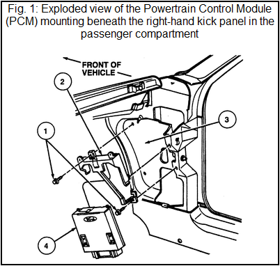
REMOVAL & INSTALLATION- Disconnect the negative battery cable.
- Remove the inside, lower cowl trim panel from the right side of the vehicle to expose the PCM.
- Disengage the wiring harness connector from the PCM by loosening the connector retaining bolt, then pulling the connector from the module.
- Remove the PCM from the bracket by pulling the unit downward.

-
To install:
- Install the PCM in the mounting bracket.
- Attach the wiring harness connector to the module, then tighten the connector retaining bolt.
- Install the right-hand cowl trim panel.
- Connect the negative battery cable.

Car Engine Sensors :
- Powertrain Control Module (PCM)
- Throttle Position (TP) sensor
- Mass Air Flow (MAF) sensor
- Intake Air Temperature (IAT) sensor
- Idle Air Control (IAC) valve
- Engine Coolant Temperature (ECT)
- Heated Oxygen Sensor (HO2S)
- Camshaft Position (CMP) sensor
- Knock Sensor (KS)
- Vehicle Speed Sensor (VSS)
- Crankshaft Position (CKP) sensor
- Engine Trouble Codes

