
CMP - Camshaft Position Sensor
Camshaft Position Sensor (CMP)
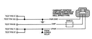
OPERATIONThe CMP sensor provides the camshaft position information, called the CMP signal, which is used by the Powertrain Control Module (PCM) for fuel synchronization. On 2 wire Sensor engines, the distributor stator or Camshaft Position (CMP) sensor is a single Hall effect magnetic switch. This is activated by a single vane, and is driven by the camshaft.
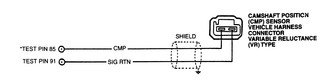
On Three Wire Sensor engines, the Camshaft Position (CMP) sensor is a variable reluctance sensor, which is triggered by the high-point mark on one of the camshaft sprockets.
The Distributor engine does not use a separate CMP sensor. It utilizes a conventional distributor, equipped with a Hall effect device, for this function.The following symptoms can be caused by intermittent wiring connections or faulty signal to the EMS.
Camshaft Position Sensor Symptoms
- Extended crank time with a cold engine
- Intermittent rough running
- Unstable idle
- Bucking
- Hesitation
- Stumble
- Chuggle
- Poor fuel economy
- Stalling on acceleration
Camshaft Position Sensor Testing
Three-Wire Sensors
- With the ignition OFF, disconnect the CMP sensor. With the ignition ON and the engine OFF, measure the voltage between sensor harness connector VPWR and PWR GND terminals (refer to the accompanying illustration). If the reading is greater than 10.5 volts, the power circuit to the sensor is okay.
- With the ignition OFF, install a break-out box between the CMP sensor and the PCM. Using a Digital Volt-Ohmmeter (DVOM) set to the voltage function (scale set to monitor less than 5 volts), measure the voltage between break-out box terminals 24 and 40 with the engine running at varying RPM. If the voltage reading varies more than 0.1 volt, the sensor is okay.
Two-Wire Sensors
- With the ignition OFF, install a break-out box between the CMP sensor and PCM.
Using a Digital Volt-Ohmmeter (DVOM) set to the voltage function (scale set to monitor less than 5 volts), measure the voltage between break-out box terminals 24 and 46 with the engine running at varying RPM. If the voltage reading varies more than 0.1 volt AC, the sensor is okay.
Camshaft Position Sensor Replacement
REMOVAL & INSTALLATION
- Disconnect the negative battery cable.
- Remove the ignition coil, radio capacitor and ignition coil bracket.
- Disengage the wiring harness connector from the CMP sensor.
NOTE: Prior to removing the camshaft position sensor, set the No. 1 cylinder to 10°After Top Dead Center (ATDC) of the compression stroke. Note the position of the sensor's electrical connection. When installing the sensor, the connection must be in the exact same position.
- Position the No. 1 cylinder at 10°ATDC, then matchmark the CMP sensor terminal connector position with the engine assembly.
- Remove the camshaft position sensor retaining screws and sensor.
- Remove the retaining bolt and hold-down clamp.
NOTE: The oil pump intermediate shaft should be removed with the camshaft sensor housing.
- Remove the CMP sensor housing from the front engine cover. To remove the 3.8L engine's CMP sensor, first locate it at the front of the engine block . . . then detach the wiring harness connector from the sensor. Remove the hold-down bolt and washer . . . then pull the sensor and housing out of the engine front cover
-
To install:
- If the plastic locator cover is not attached to the replacement camshaft position sensor, attach a synchro positioning tool, such as Ford Tool T89P-12200-A or equivalent. To do so, perform the following:
- Engage the sensor housing vane into the radial slot of the tool.
- Rotate the tool on the camshaft sensor housing until the tool boss engages the notch in the sensor housing.
NOTE: The cover tool should be square and in contact with the entire top surface of the camshaft position sensor housing.
- Transfer the oil pump intermediate shaft from the old camshaft position sensor housing to the replacement sensor housing.
- Install the camshaft sensor housing so that the drive gear engagement occurs when the arrow on the locator tool is pointed approximately 30°counterclockwise from the face of the cylinder block. (The sensor terminal connector should be aligned with its matchmarks.)
- Install the hold-down clamp and bolt, then tighten the bolt to 15–22 ft. lbs.(20–30 Nm).
- Remove the synchro positioning tool.
WARNING
If the sensor connector is positioned correctly, DO NOT reposition the connector by rotating the sensor housing. This will result in the fuel system being out of time with the engine. This could possibly cause engine damage. Remove the sensor housing and repeat the installation procedure beginning with Step 1. - Install the sensor and retaining screws, and tighten the screws to 22–31 inch lbs. (2–4 Nm).
- Attach the engine control sensor wiring connector to the sensor.
- Install the ignition coil bracket, radio ignition capacitor and ignition coil.
- Connect the negative battery cable.
A camshaft is a shaft to which a cam is fastened or of which a cam forms an integral part.(source wiki)
What do Camshafts do?Inside an engine are valves that open and close to allow fuel in and exhaust out of each cylinder. The rotation of the camshaft is what determines when the valves open and close. It is important to have the camshaft timing perfect. The camshaft has a sensor that tells the engines computer when to spray fuel from the injector so that it happens at the same time the intake valve is opened by the camshaft

Car Engine Sensors :
- Powertrain Control Module (PCM)
- Throttle Position (TP) sensor
- Mass Air Flow (MAF) sensor
- Intake Air Temperature (IAT) sensor
- Idle Air Control (IAC) valve
- Engine Coolant Temperature (ECT)
- Heated Oxygen Sensor (HO2S)
- Camshaft Position (CMP) sensor
- Knock Sensor (KS)
- Vehicle Speed Sensor (VSS)
- Crankshaft Position (CKP) sensor
- Engine Trouble Codes